


Enhanced Air Distribution for Cleanliness in Operating Rooms
Advanced air distribution technologies for enhanced cleanliness and energy savings in operating rooms
ABSTRACT
This study investigates the impact of advanced air distribution technologies on cleanliness and energy efficiency of operating rooms. A compound laminar airflow ceiling (CLAC) was developed and evaluated using computational fluid dynamics (CFD) simulations, experimental measurements, and field tests. Results show that the CLAC significantly improves air quality and reduces energy consumption compared to standard laminar flows. The study indicates potential energy savings of up to 40%.
Keywords
air distribution, cleanliness, energy savings, operating rooms, computational fluid dynamics
Introduction
With increasing demands for clean and controlled environments for patients, from healthcare to pharmaceuticals, the importance of efficient HVAC solutions is increasing. Operating theatres (OT) require specific building and technology systems and procedures that minimise the risk of airborne contamination and help to ensure the highest standards of patient safety. Contamination of the operating theatre, and especially the patient’s operating field, can be eliminated by air flowing around or, better, air conditioning. This space is referred to as a clean room. The introduction of solid aerosol particles in the air is controlled according to predetermined limits. Particles are emitted into the environment by personnel, technology, maintenance and equipment. These particles must be continuously removed from the air.
| Size | Maximum particles count per m³ equal or greater than |
|---|---|
| 0.5 µm | 3 200 000 |
| 1.0 µm | 1 000 000 |
| 5.0 µm | 29 000 |
| 10.0 µm | 3 200 |
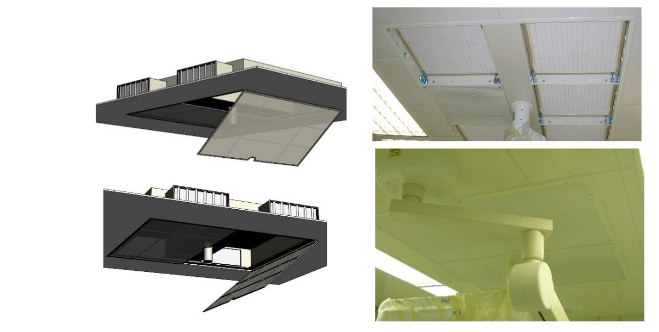
Presently, there is a demand for higher quality services, and technology for the implementation and use of operating theatres. The Society has made significant progress in terms of technology for the implementation and use of operating theatres. The risk of infection during patient surgery, where sensitive internal organs are exposed and can be more easily infected by microbial particles from the surrounding environment, has been significantly reduced. The use of a laminar ceiling is intended to ensure the highest environmental cleanliness in the operating field. Many years of use of this system have proven its functionality. Even so, the risk of infection, as well as the flow of air, cannot be completely eliminated. This research aims to discover the possible shortcomings of the use of CLAC air conditioning using a LAC and prototype CLAC model.
First and foremost, the most important thing is to describe the problem and set the objectives. It is hypothesized that the use of current laminar ceilings can be further improved to improve the efficiency of air exchange in the operating room. The idea of improving efficiency is to improve the air quality in the operating room and improving the economics of both the design and operation of the air handling equipment.
The study can thus serve two objectives. For computational modelling should be used model that corresponds to the currently built operating theatres, which generally consist of 5x5x3 m. In comparison to traditional laminar airflow systems, the new technology systems have different characteristics, such as tables, ventilation and patient anaesthesia devices and similar. For the boundary conditions of the simulation, steady three-dimensional airflow with turbulence influence was chosen. The Realizable K-Epsilon model was chosen as the turbulence model, and the Two-Layer All y Wall Treatment model was chosen for the boundary layer. The air was modelled as an ideal gas, the flow characteristics of this distribution element in its standard configuration.
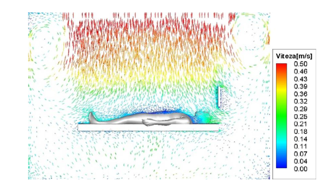
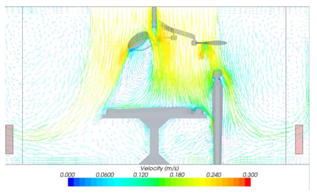
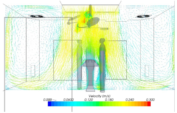
Clearly visible in the simulation is the similarity with the simulation of earlier projects. The highest air velocity is found in the operating field, on the floor and near the edge of the main extraction area. The smaller and secondary circulation areas are the air profile of this room. In Fig 8, a 3D model representation of the main circulation is shown.
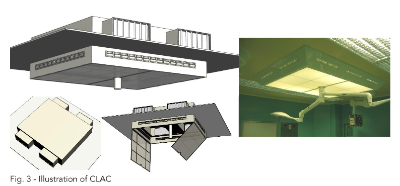
In both cases of the location of the extraction end, there is an area visible around the perimeter of the room. Due to the visual profile of this room, it can be called the main circulation area. In Fig 8, this area is shown on the ground.
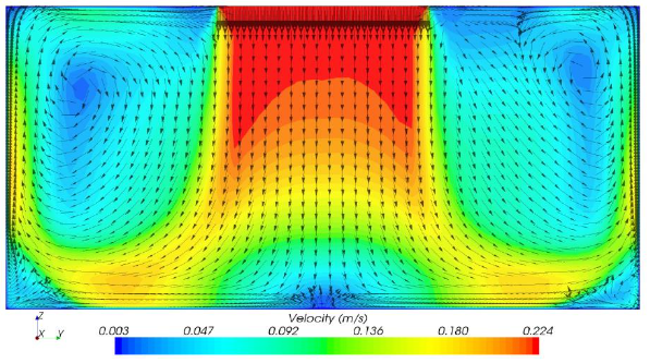
In general, the area of the clean zone, i.e. the area that is completely flooded by the supply air and mixed with the room air, is not identical to the dimensions of the air-flow supply element – the laminar element part, dominated by inertial forces. The edge of the main supply air flow, due to the viscosity of the air, turbulence is generated and the mixing with the ambient air takes place; this creates a displacement in ventilation. The viscosity of the air is also a crucial factor in the airflow.
Based on the calculations of heat, steam and electricity consumption required for air transport, the clean rooms can be classified according to the current energy consumption in MWh/year and their impact on the operation of the considered facilities. The cleanliness class for an aseptic OT is given as ≥ 2400 m³/h or an exchange rate of at least 20 times per hour, while for a superaseptic OT with an exchange rate of at least 30 times per hour, the clean air class is defined as ≥ 600 m³/h or an exchange rate of at least 30 times per hour.
| Clean room class according to Czech standard | Energy consumption in MWh/year |
|---|---|
| Aseptic | 0.088 |
| Superaseptic | 0.088 + 0.1 |
Optimising the air distribution therefore means establishing a flow pattern that reduces the mixing of secondary polluted air into the primary air stream. In addition, if the ventilation efficiency is increased, it will be possible to reduce the supply air flow rate, resulting in a reduction in the energy consumption of the air handling unit.
Discussion
This study demonstrated that compound laminar airflow ceiling (CLAC) achieves a significant reduction in the amount of solid aerosol does not degrade the OT equipment or burden the air handling equipment (the method used does not foul the laminar fabric), yet it is sufficient to visualize the flow at characteristic points in the space.
Acknowledgement
Acknowledgement is expressed of the support from the Faculty of Civil Engineering – Brno University of Technology, and the project “Research on environmentally sustainable systems and technologies for building services”, Grant No. FAST-S-24-8505.
Conflict of Interest
None.
References
- Balaras CA, Daskalakis G, Egaia A. HVAC and indoor environment: A review. Energy Build. 2007; 39(1): 470-480. doi:10.1016/j.enbuild.2006.10.021.
- Usdowski WL. Clean Room Technology. Technology Utilization Division, National Aeronautics and Space Administration; 1969.
- VDI 2083. Cleanroom technology—Particulate air cleanliness classes. VDI-GESELLSCHAFT BAUEN UND GEBÄUDETECHNIK. 2022.
- ISO. Cleanrooms and associated controlled environments—Classification of air cleanliness by particle concentration. ESN EN ISO 14644-1. Prague: The Czech Institute for Standardization, Metrology and Testing; 2016.