


Stress Corrosion in Magnesium Alloys: Analysis & Modeling
Experimental analysis and computational modelling of stress corrosion cracking and its influence on the structural integrity and mechanical properties of the magnesium alloy WE43
Geraldine Hincapie Diaz¹, André Ferreira Costa Vieira², Carlos Alberto Della Rovere³, Marcelo Leite Ribeiro¹
- Aeronautical Engineering Department / São Carlos School of Engineering / University of São Paulo – Av. João Dagnone, 1100 – Jardim Santa Angelina – São Carlos, SP, Brasil – 13563-120.
- Center for Mechanical and Aerospace Science and Technologies (C-MAST-UBI) / Universidade da Beira Interior/ R. Marquês D’Ávila e Bolama, 6201-001 Covilhã, Portugal.
- Federal University of São Carlos / Rodovia Washington Luís, km 235 – São Carlos, SP, Brasil – 13565-905.
OPEN ACCESS
PUBLISHED: 31 July 2024
CITATION: Diaz, G., H., Vieira, A., F., C., et al., 2024. Experimental analysis and computational modelling of stress corrosion cracking and its influence on the structural integrity and mechanical properties of the magnesium alloy WE43. Medical Research Archives, [online] 12(7).
https://doi.org/10.18103/mra.v12i7.5690
COPYRIGHT: © 2024 European Society of Medicine. This is an open-access article distributed under the terms of the Creative Commons Attribution License, which permits unrestricted use, distribution, and reproduction in any medium, provided the original author and source are credited.
DOI https://doi.org/10.18103/mra.v12i7.5690
ISSN 2375-1924
ABSTRACT
Magnesium alloys have been widely studied as biodegradable metals due to their low density and fast dissolution properties, making them a promising alternative for use as medical support implants. Their compatibility and degradation in the human body eliminate the need for a second surgery. However, magnesium alloys must maintain their mechanical integrity during the healing period. Despite their generally low corrosion resistance, they are highly susceptible to stress corrosion, which can lead to premature and sudden fractures of the implant. This susceptibility poses a significant challenge to their widespread use, underscoring the importance of analyzing their behavior in corrosive environments to understand their effects on mechanical properties and structural integrity. Computational modeling, particularly using “Digital Twin,” plays a crucial role in orthopedic implant design, allowing for easier and faster optimization of the final shape based on criteria such as strength and stiffness, while ensuring compatibility with the bone healing process. This study aims to characterize and experimentally analyze the effects of stress corrosion on the WE43 alloy. Constant load tests were conducted using a portable and adaptable device equipped with compression springs to apply tensile force. Specimens were immersed in Simulated Body Fluid (SBF) to replicate the corrosive environment. A numerical corrosion model was developed to predict strength and mass loss, considering the effect of local stress on corrosion rate. The calibration of material model parameters was based on experimental results, with the numerical approach extendable to generic geometries. Consequently, the proposed numerical model proved to be an efficient tool for evaluating the structural integrity of biodegradable magnesium alloys and bone-implant assemblies, offering potential for use in designing optimized orthopedic implants. The study concluded that the simultaneous effect of stress and the corrosive environment (stress corrosion) was the primary cause of mechanical property loss.
Keywords: Magnesium alloy, WE43, Stress Corrosion Cracking, Biodegradable materials, Computational modelling.
surrounding bodily fluid. For instance, implants with a larger grain size or a higher concentration of intermetallic precipitates are more prone to SCC. Furthermore, implants subjected to elevated levels of stress or exposed to chloride ions are at an increased risk of SCC¹². There are several key mechanisms involved in SCC:
• Anodic dissolution: It is the initial stage in all corrosion processes. It entails the oxidation of magnesium atoms on the implant’s surface, resulting in the formation of magnesium ions. These ions dissolve in the surrounding body fluid. Concurrently, the released electrons from this process reduce hydrogen ions in the body fluid, generating hydrogen gas. The hydrogen gas can diffuse into the magnesium alloy, leading to hydrogen embrittlement¹².
• Hydrogen embrittlement: It occurs when hydrogen atoms diffuse into the metal and form hydrogen bubbles at grain boundaries. These hydrogen bubbles weaken the grain boundaries, making the metal more susceptible to cracking.
• Transgranular SCC: Takes place within the grains of the magnesium alloy. It begins with the formation of microcracks at grain boundaries or other microstructural defects. These microcracks then propagate through the grains under the combined influence of stress and corrosion¹³.
• Intergranular SCC: Intergranular SCC occurs along the grain boundaries of the magnesium alloy. It commences with the formation of a corrosion product at the grain boundaries. This corrosion product weakens the grain boundaries, rendering them susceptible to cracking¹³.
Studies of magnesium alloys have demonstrated that materials used as implants are not only subject to general corrosion mechanisms but also experience biomechanical stresses within the human body. These stresses include both compressive and tensile forces. For instance, the knee joint operates in a complex mechanical environment encompassing activities such as rotation, flexion, and extension. In this scenario, the highest tensile stress occurs in the anterior cruciate ligament (ACL), measuring approximately 15 MPa¹⁴. Similarly, a hip implant during normal gait can endure loads of approximately four times the body weight. In contrast, a cardiovascular stent continuously faces cyclic loads due to the beating heart¹⁵.
When a magnesium alloy sample is subjected to stress in the presence of a corrosive environment, such as body fluid or saline solutions that simulate human body conditions, stress application leads to the formation of micro-cracks on the sample’s surface. These micro-cracks become preferential sites for localized corrosion and stress corrosion, as explained by Fairman and West¹⁵. During this process, magnesium ions dissolve in the corrosive environment, resulting in a reduction of the specimen’s cross-sectional area and an increase in stress at the microcrack locations. Consequently, crack propagation accelerates, leading to specimen failure, even at stress levels below the material’s yield strength, as observed by Winzer.¹²
Therefore, it is essential to understand the mechanisms of stress corrosion in magnesium alloys to enhance the durability and reliability of implants made from this material. Numerous studies focus on the effects of stress corrosion, characterizing the mechanisms and degradation rates of magnesium alloys in vivo and in corrosive environments similar to physiological conditions (in vivo), simulating them in silico through finite element analysis⁵˒⁶˒¹⁶. In general, finite element analysis is recognized as a powerful tool in the development of orthopedic products. The primary use of computational analyses occurs in evaluating the performance of devices in the early stages of development, allowing for improvements and optimizations in the design prior to prototype construction. This results in increased efficiency, cost reduction, and a decrease in the number of laboratory mechanical tests and in vivo experiments¹⁷.
Given the above and aiming to address the deficiencies observed in magnesium alloys used as biodegradable materials, it is crucial to implement and experimentally validate a finite element model capable of capturing the mechanical properties of the material. This model should also predict its behavior under stress corrosion conditions similar to those within the human body. The outcomes of this research could have significant implications for the utilization of magnesium alloys in implants and may offer relevant data for the development of safer and more durable medical devices.
2. Methods
2.1 SAMPLE
The magnesium alloy WE43MEO, manufactured by Meotec GmbH (Germany) and supplied by Fort Wayne Metals (USA), with the following chemical composition (wt. %) was used as material: Mg – bal, Y – 4.1, RE – 4.0, Zr – 0.5. The material was supplied in wire form, with a diameter of 0.88 mm. In order to anneal the material, relieve internal stresses, and enhance its ductility and toughness, it has been chosen to perform a heat treatment at 400°C for 15 minutes¹⁸–²⁰.
2.2 STRESS CORROSION TESTING
Following the heat treatment, polymeric tabs were attached to the specimen’s tips to avoid slippage and stress concentration near the grips, to ensure that the specimens rupture occurs in the middle of the specimen. Tensile tests were conducted to assess the mechanical properties of the magnesium alloy. An INSTRON universal testing machine was employed, and the tests were performed at a controlled speed of 1 mm/min. Each specimen possessed a total length of 80 mm and a useful length of 50 mm, as illustrated in Figure 1.
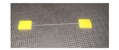
Figure 1: Tensile test specimen.
Stress corrosion tests are commonly conducted using constant load tests. In this type of test, the material’s tensile strength is sustained until failure occurs at different fixed stress levels within a corrosive environment. The objective is to identify the stress limits and evaluate the time to failure, particularly when failure tends to be non-existent. In the case of the WE43 alloy, these tests are performed under the same conditions and in a corrosive environment.
For conducting stress corrosion experiments, a device based on the C test described by Grogan is used as a reference¹⁶. This device is designed to generate tensile stress in the specimens. The device structure is made of a polymer, specifically polyacetal, chosen to minimize the risk of galvanic corrosion. Stainless steel guides are employed to ensure that the specimens are loaded purely in uniaxial tension (Figure 2).
In the device, two calibrated compression springs are used to apply the load to the specimens. The springs are compressed to a defined length based on the desired load value. This is achieved by tightening two bolts that pass through the inner diameter of the springs, securing the specimen in place. To release the load from the springs onto the specimen, the screws are loosened. It is worth noting that the gradual elongation of the specimen in the solution has a minimal effect on the applied load, with a reduction of less than 1.1 N (1.8% of the lowest applied load) observed.
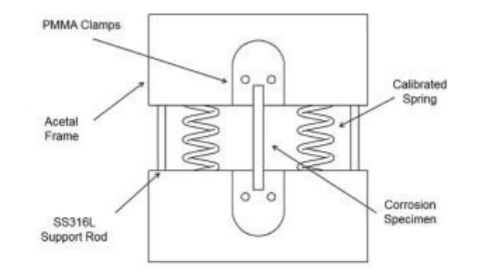
Figure 2: Constant load test device.
For immersion stress corrosion biodegradation tests, a conventional simulated body fluid (c-SBF) is used as the electrolyte, produced based on Table 1²¹. This choice is based on its widespread usage and its favorable ionic and pH stability for storage.
Table 1: Quantity of reagents for SBF preparation.
| Reagent | Purity (%) | Amount |
|---|---|---|
| NaCl | >99.5 | 8.036 g |
| NaHCO₃ | >99.5 | 0.352 g |
| KCl | >99.5 | 0.225 g |
| K₂KPO₄ * 3H₂O | >99.0 | 0.230 g |
| MgCl₂*6H₂O | >98.0 | 0.311 g |
| 1.0 M * HCL | – | 40 ml |
| CaCL₂ | >95.0 | 0.293 g |
| Na₂SO₄ | >99.0 | 0.072 g |
| TRIS | >99.9 | 6.063 g |
| 1.0 M * HCL | – | 0.2 ml |
The specimens used in these tests, referred to as SPs, have a diameter of 0.88 mm and a usable length ranging between 65 mm and 69 mm. To begin the testing process, it is necessary to prepare the specimens by subjecting them to chemical cleaning with 20% chromic acid. This step aims to remove surface oxides from the specimens. Following the cleaning process, the mass of each specimen should be measured and documented to enable identification. Subsequently, the SPs are assembled in the testing device.
The mass loss and corrosion rate of the material when immersed in the simulated body fluid (SBF) were measured using the hydrogen evolution method. This involved employing test specimens (SPs) with dimensions of 0.88 mm × 100 mm. A system consisting of a container, a device to maintain tension on the SPs, a funnel, and a graduated cylinder of 15 ml, with an accuracy of 0.2 ml, all made of glass, was utilized, as illustrated in Figure 3. The funnel and graduated cylinder assembly were positioned at a significant height relative to the bottom of the main container, allowing the free circulation of SBF. For every 3 test specimens, a tensile load was applied, with load levels fluctuating between 50% and 70% of the yield strength of the alloy.
Before and after the immersion period, the test specimens underwent chemical cleaning with 20% chromic acid, followed by distilled water. Finally, the mass loss (Delta W) was calculated from the measured volumes using “Eq. (3)”, and corrosion rate (CR) was determined through “Eq. (4)”.
(3)
ΔW = (1.085Vₕ) / Pₐₜₘ
where, ΔW is the mass loss, in mg; Vₕ is the volume of hydrogen released, in ml; Pₐₜₘ is the atmospheric pressure, in atm.
(4)
CR = Δw / (AΔt)
where, A is the original area exposed to the corrosive medium, in cm²; t is the exposure time, in h.
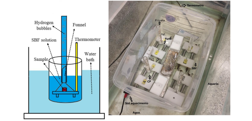
Figure 3: System for measuring magnesium biodegradation using the hydrogen evolution method.
After the immersion period, the specimens are removed from the corrosion electrolyte. They undergo cleaning once again, this time using 20% chromic acid, followed by rinsing with distilled water. This cleaning procedure ensures the removal of any corrosion products present on the surface of the SPs.
2.3 DETERMINATION OF THE INFLUENCE OF STRESS CORROSION CRACKING ON MECHANICAL PROPERTIES
To determine the influence of stress corrosion cracking (SCC) on mechanical properties, tests similar to those described in the previous section were conducted. In this context, the specimens (CPs) were placed in the SCC device and immersed in SBF for different intervals (6 h, 12 h, 24 h, 48 h). All CPs were subjected to a stress of 110 MPa, representing 50% of the alloy’s yield strength. This stress level was chosen to ensure that the CPs could withstand up to 48 hours without fracturing. The dimensions of the CPs used were Ø0.88 mm × 100 mm.
As suggested by Saconi,²² it is advisable to apply a protective layer of Polytetrafluoroethylene (PTFE) to ensure that failure during the test occurs exclusively in the central region. Thus, the effective area of the CP was limited to a total length of 50 mm, resulting in a surface area subject to corrosion of 1.32 cm². A total of 3 CPs (n = 3) were used for each condition.
After removal from the SBF immersion bath, the cleaning process with a 20% chromic acid solution was repeated, followed by rinsing with distilled water to remove all possible corrosion products from the CP surfaces. Additionally, all CPs were properly identified and weighed using a precision balance. Subsequently, tensile tests were conducted to determine the mechanical properties of the corroded alloy.
2.4 COMPUTATIONAL MODELLING
The computational simulation of the biodegradation of magnesium alloys is a crucial tool in the design and development of new implant materials, as it enables an efficient and rapid assessment of the structural behavior of a component after partial degradation. This is practical for in vivo and in vitro corrosion studies. Furthermore, it significantly reduces both time and costs compared to traditional methods and diminishes the need for animal testing.
Biodegradation simulation models can be categorized into phenomenological models and physical models. For this study, the use of phenomenological models was chosen, which focus on the structural effects resulting from degradation without explicitly modeling its progression.
Therefore, the corrosion damage model was implemented through a Fortran® language subroutine called VUMAT (User Material Subroutine), compatible with the commercial finite element software Abaqus®/Explicit (Dassault Systemes, USA). The utilization of VUMAT with Abaqus®/Explicit allows the user to define constitutive models for materials of varying complexities, different from those available in the software’s material library.
2.4.1 Mathematical model description
Localized corrosion such as pitting and stress corrosion was implemented using a non-local integration formulation to mitigate the mesh size influence on results, based on the Continuum Damage Mechanics (CDM). This model incorporated the von Mises elastoplastic formulation with isotropic hardening to simulate the material’s mechanical behavior. In this way, the model can simulate mass loss during the corrosion process as well as the effects of small corrosion-induced defects on the material’s mechanical integrity.
The implemented corrosion model consists of three components:
• Pre-processor: This component operates before the main Abaqus® analysis and is responsible for preparing the input file for the main analysis based on the .inp file. The pre-processing stage involves acquiring vital data for model execution. It generates the connectivity map of the elements, identifying neighboring elements for each element. Neighboring elements are defined as those sharing a face. It determines which elements are located on the model’s surface and assigns initial local pitting parameters to each element situated on the initial model surface.
• VUMAT: this is where the main Abaqus/Explicit analysis is executed, describing the constitutive behavior of the magnesium alloy coupled with a subroutine “DAMAGE,” which is used to update the damage parameter D. Additionally, the information contained in the input file is read through the VEXTERNALDB subroutine and saved in global variables using the MODULE function present in FORTRAN 90. The VEXTERNALDB subroutine is automatically called by the main Abaqus analysis at different points: at the beginning and end of the analysis, at the beginning and end of each step, and before, at the beginning and end of each increment. In each call, this subroutine allows for opening and closing external files for data exchange within the Abaqus analysis and between subroutines through global variables.
• The subroutine “DAMAGE,” called by VUMAT, has the function of updating the damage parameter D using information contained in global variables through the MODULE function. For example, the connectivity map, coordinate map, and values of local parameters such as λc and αc for all elements are utilized to calculate non-local average parameters δeq and λ. The subroutine’s operation is presented in Figure 5. Thus, when an element is completely corroded, the subroutine executes the removal of the element in the mesh for the Abaqus solver. Afterward, the DAMAGE function updates the model’s surface and triggers the transfer mechanism of the pitting parameter from the corroded element to its neighbors, updating the global variables of the MODULE. Finally, after the Damage parameter calculation, the subroutine computes the percentage of mass corroded for the element.
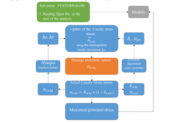
Figure 4. VUMAT processing flowchart.
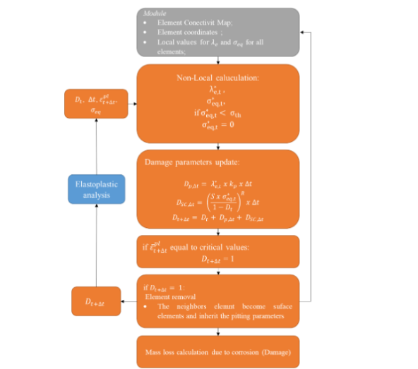
Figure 5. VUMAT/DAMAGE processing flowchart.
2.4.2 Simulation and Calibration of Experiments in the Corrosion Model
For the simulation, a solid with dimensions Ø0.88 × 10 mm is modeled using Abaqus software. It has the same cross-sectional area as the test specimen used in the experiments but with a reduced length. A mesh with linear hexahedral elements with 8 nodes, (C3D8R), representing three-dimensional, deformable, hexagonal solids, composed of elements with dimensions of 0.07 mm, totaling 20878 elements. The choice of the 0.07 mm dimension is in accordance with the range of values commonly used in the literature for simulating corrosion in biodegradable magnesium alloys²³.
Previously, in the work of Saconi,²² the parameters of the pitting localized corrosion model (ψ, θ, ν, and kp) were iteratively calibrated based on the experimental corrosion results conducted in the same study until a good fit between the simulation and experimental results is achieved. This occurs when the simulated mass loss curve versus corrosion time qualitatively corresponds to the trend and quantitatively matches the average corrosion rate from previous corrosion experiments.
On the other hand, the calibration of the parameters of the stress corrosion model, R and S, is conducted based on the data obtained in experiments, according to the difference between the mass losses of localized pitting corrosion and immersed stress corrosion. Therefore, the discrepancy between the two experiments is attributed to stress corrosion damage. The value of σth is adopted as 50% of the material’s yield stress, a value associated with the occurrence of stress corrosion in different magnesium alloys.
This process was carried out iteratively, involving the simulation of the test specimen corrosion over a period of 168 hours under axial loads of σ = 150 MPa, 130 MPa, and 110 MPa. As discussed earlier, the parameters R and S are closely related to the kinetics of the corrosive process, being dependent on the corrosion environment.
3. Results
3.1 Mechanical Characterization
Initially, a uniaxial tension test is performed to verify the mechanical properties of the material and validate the subjection method in the stress corrosion tester, because there may be slippage or excessive force concentrations at the ends where the specimen is subjected. To mitigate these issues, it is proposed to attach polymeric clamps or tabs to the specimens, as illustrated in Figure 6. Figure 7 shows the stress-strain curve obtained from the tensile test conducted before and after the heat treatment.
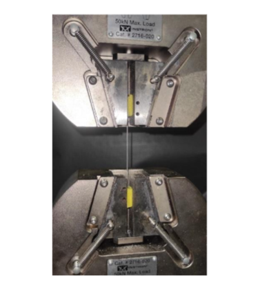
Figure 6: Setting up the tensile test on the universal machine.
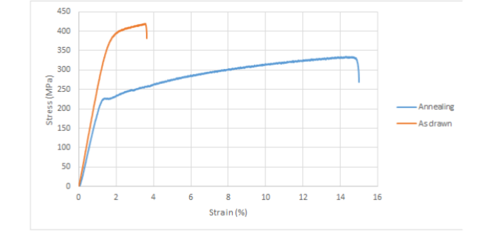
Figure 7 caption: The Figure 7 illustrates the influence of the annealing heat treatment on the stress-strain curve of WE43.
3.2 STRESS CORROSION TEST
Figure 8 presents the results of the tests until failure due to stress corrosion. The applied stress is determined as the ratio between the applied load and the cross-sectional area of the original sample. This graph allows the determination of the time to failure based on the applied load and the estimation of the threshold stress σₜₕ, representing the stress level below which stress corrosion failure does not occur²⁴.
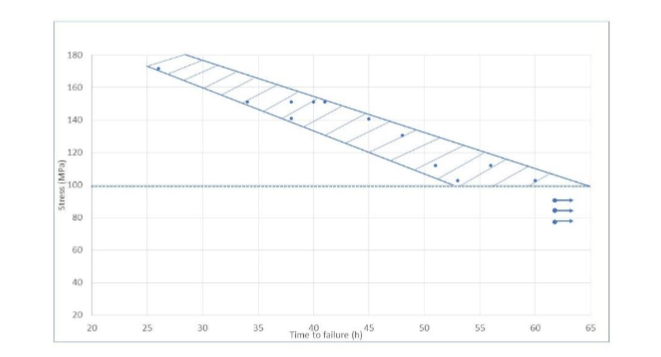
Figure 8: Time to failure and applied stress obtained in constant load tests.
Through the immersion experiments in SBF using the hydrogen evolution technique, as described in section 0.2, it was possible to calculate the corrosion rate for the WE43 alloy over a 3-day period. The results are presented in Figure 9 and Figure 10.
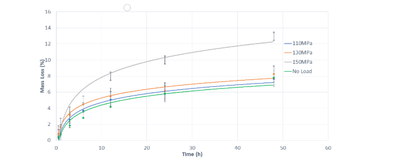
Figure 9: Mass loss (%) in function of time.
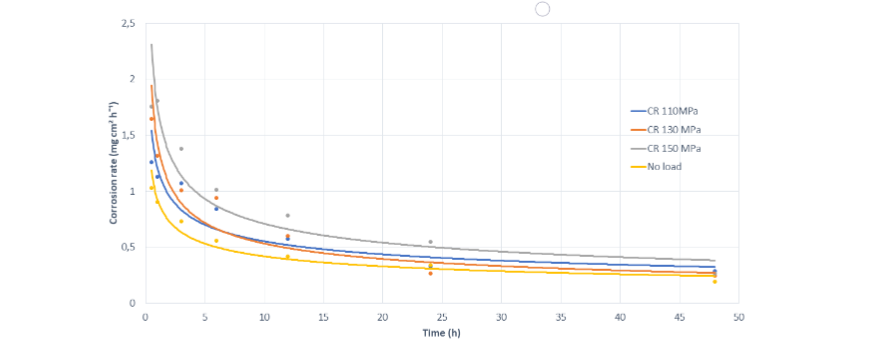
Figure 10: Corrosion rate in function of time.
3.3 FRACTURE ANALYSIS
This work will also involve the fracture surface analyses using scanning electron microscopy (SEM) on the samples which were exposed to the SCC test in the simulated body fluids (SBF). Figures 11 and 12 refer to the SP immersed in SBF and subjected to a stress of 150 MPa, which fractured at 34 hours.
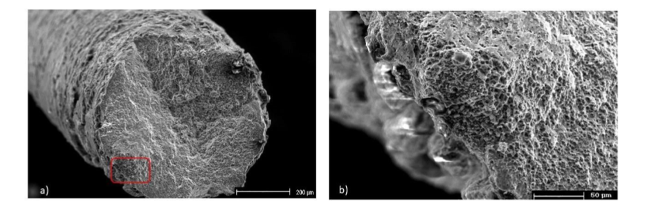
Figure 11: SEM fractographs of the sample immersed in SBF at a stress of 150 MPa:
(a) General fracture surface and
(b) cracking detail on the circumference.
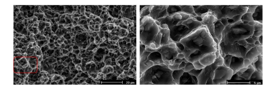
Figure 12: SEM fractographs of the sample immersed in SBF at a stress of 150 MPa:
(a) Overload site.
(b) Magnified SEM image of the overload site.
3.4 COMPUTATIONAL MODELLING
3.4.1 Stress Corrosion Model
A variation of the stress corrosion simulation was adopted by applying a constant stress to one end of the specimen and fixing the other end. The recorded values of the loading were 110 MPa, 130 MPa and 150 MPa, the same as the experimental values.
The used constraint for parameter calibration was that the specimen exhibited a mass loss of 34.3% over a period of 168 hours, f = 0.5, where both mechanisms equally contribute to the damage calculation.
At the beginning of the simulation, the values of the parameters γ and β involved in the creation and development of the localized pitting corrosion, which were previously calibrated in the work by Saconi²², were employed. It is important to note that the stress corrosion mechanism occurs due to the formation and propagation of cracks caused by localized corrosion defects or cracks resulting from hydrogen incorporation.
The parameter γ is related to the initial random value of the pitting parameter for surface elements, responsible for the distribution and homogeneity of corrosion on the initial surface of the model. On the other hand, the parameter β is related to the penetration power of corrosion into the material. Lower values of the β parameter result in slower defect evolution and more homogeneous and superficial corrosion compared to higher values.
The scale parameter of the Weibull distribution, ψ, was adopted with a value of 1. The intrinsic length, Lr, was set to 0.2 mm, and a variable kinetic corrosion parameter, kpv, was implemented as a function of time.²² The calibrated value was defined as:
kpv = 0.3125 t⁻⁰·⁶⁸
where t is the corrosion time, in hours.
For the purpose of SCC parameter calibration, the value of R was set between 2 and 4. The result showed that with values of 3 and 4, there was more localized and less homogeneous corrosion. Therefore, R = 2 was adopted, a choice supported by several authors who conducted work under similar conditions.
On the other hand, the parameter S was adjusted in the range between 0.0006 and 0.003, showing that the time to failure can be modulated through S. A small value did not result in specimen failure, only in a reduced percentage of mass loss.
To arrive at the ideal values of the parameters for the model, the simulation of the SP with a stress of 150 MPa was initiated, where 13 simulations were conducted without altering the values of R. Initially, the value of S was established as 0.00047. Then, the SP was simulated with a stress of 130 MPa, keeping the values of R and S and only changing the load. In this case, there was not an adequate correspondence in the percentage of mass loss, necessitating recalibration of the model.
A total of 65 simulations were conducted to establish the values of parameters R and S as 2 and 0.001, respectively. With these values, in the simulations of the SP with 110 MPa of stress, it was possible to reproduce the behavior of mass loss, obtaining a decrease in the percentage, which corresponds to the reduction in stress.
Considering that the model should also be able to adequately represent the behavior of mass loss and corrosion rate over time, the results were compared with the experimental section results. The adjusted values of R and S showed a good correlation between the curves of Mass Loss and Corrosion Rate versus time, both experimental and simulated.
Table 2: Calibrated parameters for the stress corrosion model
| R | S | f | corr |
|---|---|---|---|
| 2 | 0.001 | 0.50 | 0.3 |
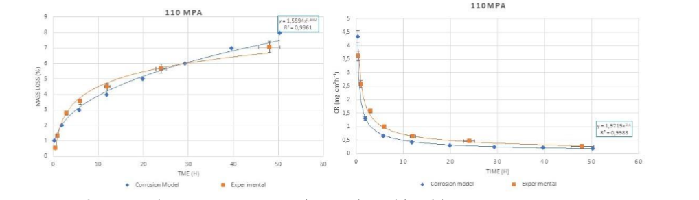
Figure 13 Mass loss curve and corrosion rate comparative between the models and the 110 MPa Stress Corrosion tests.
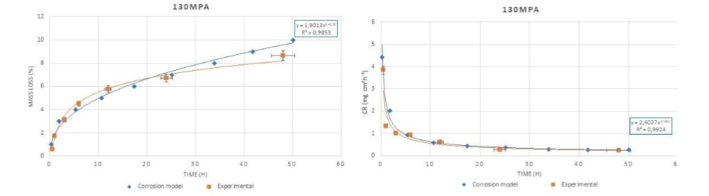
Figure 14 Mass loss curve and corrosion rate comparative between the models and the 130 MPa Stress Corrosion tests.
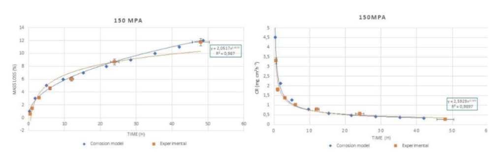
Figure 15 Mass loss curve and corrosion rate comparative between the models and the 150 MPa Stress Corrosion tests.
Additionally, it was possible to define the influence of corrosion on the mechanical strength of the material through the experimental and simulated graphs of Ultimate Tensile Strength vs. Mass Loss and Elongation vs. Mass Loss, which are presented in Figure 16 a) and b), respectively.
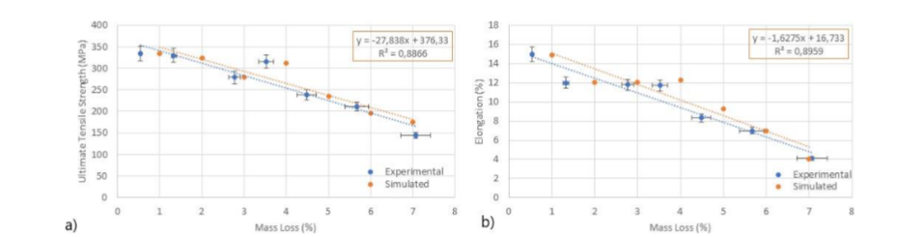
Figure 16 Influence of biodegradation on the mechanical properties of WE43 alloy.
The Figure 17 and 18 displays the simulation of the solid at different stages of stress corrosion with a load of 110 MPa and 150 MPa respectively, each with an approximate time of 6 h, 12 h, 24 h, and 48 h.
From the results, it was possible to define the influence of corrosion on the material’s mechanical strength. For each of the immersion periods, a traction test was simulated, and a stress-strain curve was generated and subsequently compared in Figure 19, where it is compared the SCC simulation with the experimental results.
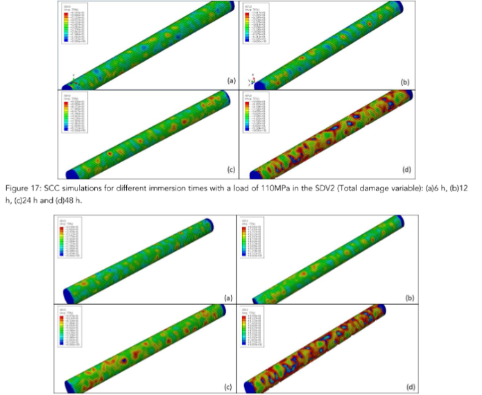
Figure 17: SCC simulations for different immersion times with a load of 110 MPa in the SDV2 (Total damage
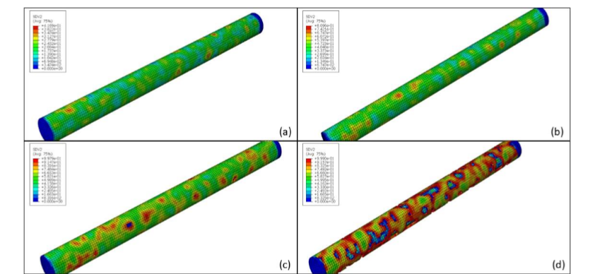
Figure 18: SCC simulations for different immersion times with a load of 150 MPa in the SDV2 (Total damage variable):
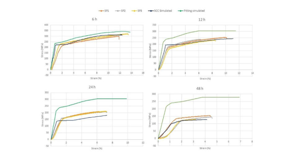
Figure 19: Stress-strain graph after different corrosion periods.
4 Discussions
4.1 MECHANICAL CHARACTERIZATION
Figure 7 illustrates the influence of the annealing heat treatment on the stress-strain curve of WE43. It is evident that annealing processes led to a substantial improvement in the alloy’s ductility. Specifically, ductility increased from 3.3% to 15% strain. However, this enhancement in ductility was accompanied by a decrease in the ultimate tensile strength of approximately 32%.
According to Mardina, annealing increases the grain size of the alloy²⁰. This can make the alloy less strong and more susceptible to creep, but it can also improve the alloy’s toughness. Annealing can enhance the corrosion resistance of the alloy by relieving internal stresses and homogenizing the microstructure.
On the other hand, in a study referenced by Yang and Mardina²⁰˒²⁵, it was observed that the annealing heat treatment leads to the following changes in the alloy. The hardness and strength of the alloy decrease. This phenomenon can be attributed to the lower dislocation density and the larger grain size. As the grain size increases, the number of grain boundaries, which act as obstacles to dislocation motion, decreases, resulting in reduced strength. However, the larger grain size and decreased dislocation density promote plastic deformation, allowing for improved plasticity and elongation before fracture¹⁴. This is particularly advantageous for this study as high deformability and resistance to cracking are required for applications involving the magnesium alloy¹⁹.
The results are consistent with those reported by Maier and with the characterization by Saconi¹⁸˒²².
Table 3 displays the material properties under the three different conditions.
Table 3: Average mechanical properties for both: As drawn and Annealed wire specimens.
| Thermal Condition | UTS (MPa) | Yield Stress (MPa) | Elongation at break (%) |
|---|---|---|---|
| As Drawn | 420.4 ± 10.3 | 389.9 ± 10.2 | 3.50 ± 1.2 |
| Annealed 400°C – 15 min | 356.7 ± 2.4 | 245.9 ± 8.5 | 15 ± 0.2 |
4.2 STRESS CORROSION TEST
In Figure (8), can be observed that the time to failure is inversely proportional to the applied stress. It can be determined that with a stress of 150 MPa, the specimens reached a fracture time of 25 hours, the specimens subjected to a stress of 150 MPa reached fracture in 40 hours, the specimens with a stress of 130 MPa reached a fracture time of 45 hours, and finally, those with a stress of 110 MPa reached fracture between 50 and 60 hours.
In all the stress corrosion cracking tests, fractures occurred for applied stresses below the yield stress of 245 MPa. The applied stresses ranged between 40% and 80% of the yield strength. This range of stress was increased due to the limited precision in applying stress to the device’s springs, as an additional millimeter of compression in the springs can lead to 10% to 15% variation in the final stress.
The Figure 9 depicts the cumulative mass loss for the specimens under stress levels of 110 MPa, 130 MPa, and 150 MPa. It can be observed that 50% of the total corrosion occurred within the first 6 hours of the test. When compared with tests conducted on unloaded samples, where 50% of the total corrosion occurs within the first 12 hours of immersion, the loaded samples exhibit a more rapid corrosion progression.²²
Additionally, comparing mass loss for each stress level, the specimens loaded with 150 MPa showed a higher percentage of mass loss by approximately 40% compared to the samples with 130 MPa and 110 MPa stresses, which exhibited similar percentages of mass loss.
In Figure 10, it can be observed that the corrosion rate exhibits a variable behavior over time. A high corrosion rate is evident in the first 12 hours of immersion, and the corrosion rate decreases over time as the sample degrades. As the coating becomes thicker, the diffusion time increases, requiring more time to reach the magnesium sample and initiate the corrosive process.
Additionally, this result demonstrates that samples subjected to higher stress (150 MPa) experienced a higher corrosion rate compared to samples loaded with 130 MPa and 110 MPa, with the behavior of the latter two being similar. This highlights that the application of higher tensile stress to magnesium samples accelerated their corrosion process.
At the three stress conditions, it is evident that the specimens experience a significant mass loss in the initial hours of the test. This can be attributed to the heat treatment process, which may promote the formation of a protective oxide layer on the surface of the alloy, thereby enhancing its resistance to corrosion in various environments. Thus, it is evident that the 400°C–15 min annealing condition not only positively influences corrosion resistance but also improves the alloy’s ductility.
4.3 FRACTURE ANALYSIS
Majority of critical parts of the fracture surface of the tested objects were observed to have “dimples”, indicating the occurrence of overload failure. Also, features of brittle fracture were founded related to second phase particles of the alloy. In the consequence, the resulted fracture specimens have brittle fracture mechanism dominated with ductile mechanism of fracture.
Patterns of both transgranular and intergranular cracking in the WE43 alloy were identified in Figures 11 and 12. The transgranular cracking took place at the peripheral regions of the alloy, whereas the intergranular cracks were generally seen on the grain boundaries of the specimen.
The cracking properties with both intergranular and transgranular cracking exhibited by these alloys validates the observations reported in the literature about magnesium alloys with rare earth elements²⁶. Previously, it has been found that transgranular cracking is associated with hydrogen processes that can be a consequence of electrochemical breakdown or the mechanical rupture of layers¹². This type of hydrogen will permeate through the alloy structure, leading eventually to embrittlement²⁷˒²⁸.
It can be inferred that the SCC test on all four SPs of WE43 alloy produced more severe embrittlement than the results of propagating cracks measured by the data in the mechanical properties test.
4.4 COMPUTATIONAL MODELLING
4.4.1 Stress Corrosion Model
The results obtained by Figures 13, 14 and 15 demonstrate a high agreement between experimental and the simulated curves of mass loss and corrosion rate. The simulations performed showed that the model is capable of accurately reproducing the behavior observed in the experimental tests, increasing or decreasing the mass loss and corrosion rate according to the variation of the applied stress. It was observed that for a higher stress of 150 MPa, the highest mass loss and corrosion rate were obtained, reaching values of 12% and 0.33 mg cm⁻² h⁻¹, respectively.
This study also presents results similar to those found in the work of Saconi²² where the curves were calibrated for a non-local model of localized pitting corrosion. However, in the present study, it was possible to implement the calibration of stress corrosion parameters in the model, resulting in an even more precise correspondence between the experimental and simulated curves for the multi-mechanism corrosion model or stress corrosion. These results highlight the robustness and effectiveness of the proposed model in predicting the behavior of stress corrosion in biodegradable magnesium systems.
As shown in Figure 16, the calibrated model accurately captures the reduction in mechanical integrity caused by corrosion, as observed experimentally, for different immersion periods. In both figures, it is noticeable in both the experimental and simulated data that an increase in the percentage of corroded mass results in a reduction in both mechanical strengths, represented by Ultimate Tensile Strength, and associated total elongation.
With Figure 18, it is possible to observe that the model can qualitatively reproduce the corrosion mechanism. To graphically compare the simulations, Figure 17 also shows the stress corrosion simulation, but with a load of 150 MPa, for the periods of 6 h, 12 h, 24 h, and 48 h. In this case, the same behavior observed in the experimental tests can be evidenced, where the mass loss and corrosion rate are similar in the first hours; however, at 24 h and 48 h, it is possible to appreciate the difference between the specimens subjected to different stresses.
It was observed that element exclusion occurred in areas of high concentrated stress, indicating that the degradation process began in areas where the specimens experienced the highest levels of stress. Over time, stress corrosion severely damaged the central part of the specimen, leading to a lack of structural integrity. These results are consistent with those evaluated in the work of Wu²⁹, which discusses the corrosion evolution of three different designs of biodegradable magnesium alloy stents.
It is evident that the material’s strength in the elastic zone decreases as the immersion time increases. Similarly, the influence of corrosion in the plastic zone is notable, significantly reducing the specimen’s deformation percentage. Table 4 summarizes the mechanical properties of the specimen for each corrosion or immersion time analyzed, which correspond with the experimental data obtained in the mechanical properties tests (Table 5).
Table 4: Mechanical properties of the specimen for each corrosion period simulated.
| Time (h) | Ultimate Tensile Strength (MPa) | Yield limit (MPa) | Deformation (%) |
|---|---|---|---|
| 6 | 335.56 | 242.29 | 12.28 |
| 12 | 244.00 | 194.50 | 11.13 |
| 24 | 181.19 | 139.91 | 7.28 |
| 48 | 126.99 | 116.05 | 4.15 |
Table 5: Summary of mechanical test results after SCC (n=3)
| Time (h) | Modulus of Elasticity (GPa) Pitting | Modulus of Elasticity (GPa) SCC | Ultimate Tensile Strength (MPa) Pitting | Ultimate Tensile Strength (MPa) SCC | Yield limit (MPa) Pitting | Yield limit (MPa) SCC | Deformation (%) Pitting | Deformation (%) SCC |
|---|---|---|---|---|---|---|---|---|
| 0 | 22.31 | — | 333.97 ± 2.4 | — | 225.45 ± 8.5 | — | 14.97 ± 0.2 | — |
| 6 | 30.6 ± 1.8 | 24.66 ± 0.59 | 313.9 ± 3.8 | 315.28 ± 9.58 | 225.6 ± 4.1 | 221.28 ± 5.02 | 8.7 ± 0.4 | 12.80 ± 0.68 |
| 12 | 27.3 ± 1.5 | 29.7 ± 5.15 | 278.9 ± 6.7 | 239.25 ± 5.67 | 198.5 ± 6.7 | 175.44 ± 5.52 | 8.0 ± 0.4 | 8.34 ± 1.32 |
| 24 | 28.2 ± 0.6 | 30.33 ± 1.71 | 291.9 ± 8.7 | 210.75 ± 1.29 | 211.0 ± 5.9 | 160.26 ± 1.32 | 10.0 ± 0.1 | 6.97 ± 0.4 |
| 48 | 25.8 ± 1.5 | 35.78 ± 3.2 | 259.2 ± 24.7 | 143.94 ± 9.36 | 201.7 ± 2.8 | 108.87 ± 16.85 | 7.0 ± 2.6 | 4.08 ± 0.58 |
As is shown in the graphs, a correlation between immersion time of the SPs and stress corrosion cracking is established. This correlation is characterized by a decrease in both the Ultimate Tensile Strength and deformation of the specimens as the immersion time extends. A comparison between the curves obtained in the stress corrosion cracking tests and in the localized pitting corrosion (green curve) also reveals the influence of stress corrosion cracking.
After 48 h the tensile strength and the yield strength for the SPs that have been pitted corroded do not decrease significantly, only suffering a reduction in their deformations. Nevertheless, SPs with a stress corrosion cracking phenomenon revealed a stronger damage in the mechanical properties from 12 hours of immersion. It is important to clarify that it was only possible to perform tests on specimens with up to 48 hours of immersion because, after this time, they can no longer maintain their structural integrity while the pitting corrosion affects the structural integrity only after 168 hours of immersion²². The same as Choudhary was obtained with the stress corrosion tests on WE43¹⁹, the test was done in air and the solution was the m-SBF, where the elongation to failure in the m-SBF solution was significantly lower compared to the test in air, thus the m-SBF embrittlement indicates.
The test results indicate that the static load in conjunction with corrosive (stress corrosion cracking) environment do increase the crack propagation (as the component loses its mechanical integrity at a faster rate than the samples without corrosion and without load (pitting corrosion)). The cracking of SPs under stress corrosion showed very high level of reduction in mechanical properties and in all the cases, the loss of strength was linearly related to the immersion time.
The evidence that the application of tensile stress to magnesium samples substantially accelerates the corrosion rate, emphasizing a critical connection between applied stress and material degradation in magnesium alloys. This finding is pivotal for gaining insights into how stress influences corrosion resistance in such alloys.
Furthermore, it was evident that the time to fracture for the samples exhibited an inverse relationship with the applied stress. Higher stress levels resulted in shorter fracture times, a crucial aspect for evaluating the longevity of magnesium components exposed to stress in corrosive environments.
The corrosion rate fluctuated during the immersion tests in SBF solution, displaying an initial high corrosion rate that gradually decreased over time. This observation suggests the significant role of a protective layer formation in mitigating the corrosive process.
In the constant load Stress Corrosion Cracking (SCC) experiments, fractures consistently occurred below the yield strength in all tested specimens, with applied loads ranging between 40% and 80% of the yield strength. Notably, visible signs of corrosion, including pitting and the development of a coarse oxide layer on the material surface, were observed in all fractured specimens. The consistent occurrence of fractures below the yield strength in diverse conditions underscores the presence of the SCC phenomenon.
5. Conclusions
In conclusion, the conducted tests provided clear …
Conflict of Interest:
None.
Funding:
The authors are very grateful for the support granted by the Center for Mechanical and Aerospace Science and Technologies (C-MAST-UBI), through the Project reference UIDB/00151/2020, funded by the Fundação para a Ciência e a Tecnologia, IP/MCTES through national funds (PIDDAC), and DOI: 10.54499/UIDB/00151/2020.
Acknowledgements:
None.
References
1. Mordike B, Ebert T. Magnesium: properties—applications—potential. Materials Science and Engineering: A. 2001;302(1):37–45.
2. Li L, Gao J, Wang Y. Evaluation of cyto-toxicity and corrosion behavior of alkali- heat-treated magnesium in simulated body fluid. Surface and Coatings Technology. 2004;185 (1):92-98.
3. Staiger MP, Pietak AM, Huadmai J, Dias G. Magnesium and its alloys as orthopedic biomaterials: A review. Biomaterials. 2006;27 (9):1728-1734.
4. Saris NEL, Mervaala E, Karppanen H, Khawaja JA, Lewenstam A. Magnesium: An update on physiological, clinical and analytical aspects. Clinica Chimica Acta. 2000;294(1):1-26.
5. Choudhary L, Raman RS. Magnesium alloys as body implants: Fracture mechanism under dynamic and static loadings in a physiological environment. Acta Biomaterialia. 2012;8(2):916-923.
6. Gastaldi D, Sassi V, Petrini L, Vedani M, Trasatti S, Migliavacca F. Continuum dam- age model for bioresorbable magnesium alloy devices—Application to coronary stents. Journal of the mechanical behavior of biomedical materials. 2011;4(3):352–365.
7. Esmaily M, Svensson J, Fajardo S, et al. Fundamentals and advances in magnesium alloy corrosion. Progress in Materials Science. 2017;89:92-193.
8. Song G, Atrens A. Understanding magnesium corrosion—a framework for improved alloy performance. Advanced engineering materials. 2003;5(12):837–858.
9. Pereira GS, Koga GY, Avila JA, et al. Corrosion resistance of WE43 Mg alloy in sodium chloride solution. Materials Chemistry and Physics. 2021;272:124930.
10. Seitz JM, Lucas A, Kirschner M. Magnesium-based compression screws: a novelty in the clinical use of implants. Jom. 2016;68:1177–1182.
11. Windhagen H, Radtke K, Weizbauer A, et al. Biodegradable magnesium-based screw clinically equivalent to titanium screw in hallux valgus surgery: Short term results of the first prospective, randomized, controlled clinical pilot study. Biomedical engineering online. 2013;12:62.
12. Winzer N, Atrens A, Song G, et al. A critical review of the stress corrosion cracking (SCC) of magnesium alloys. Advanced Engineering Materials. 2005;7(8):659–693.
13. Abdalla M, Joplin A, Elahinia M, Ibrahim H. Corrosion Modeling of Magnesium and Its Alloys for Biomedical Applications: Review. Corrosion and Materials Degradation. 2020;1 (2):219–248.
14. Gao Y, Wang L, Li L, et al. Effect of stress on corrosion of high-purity magnesium in vitro and in vivo. Acta Biomaterialia. 2019;83:477-486.
15. Fairman L, West JM. Stress corrosion cracking of a magnesium aluminium alloy. Corro- sion Science. 1965;5(10):711–716.
16. Grogan J, O’Brien B, Leen S, McHugh P. A corrosion model for bioabsorbable metallic stents. Acta Biomaterialia. 2011;7(9):3523-3533.
17. Ismail Bin Ismayatim I. Finite Element Analysis of Corroded Pipelines. 2009.
18. Maier P, Griebel A, Scheffler O, Schaffer J. Remaining strength of cold drawn and aged WE43 wires after corrosion. European cells materials. 2015;30:47.
19. Choudhary L, Singh Raman R, Hofstetter J, Uggowitzer PJ. In-vitro characterization of stress corrosion cracking of aluminium-free magnesium alloys for temporary bio-implant applications. Materials Science and Engineering: C. 2014;42:629-636.
20. Mardina Z, Venezuela J, Sjafrizal T, Shi Z, Dargusch MS, Atrens A. The influence of strain rate and annealing heat treatments on the corrosion and mechanical properties of WE43 and Zn7Ag biodegradable wires for application in soft tissue reconstructions. Materials Today Communications. 2023;35:105809.
21. Oyane A, Kim HM, Furuya T, Kokubo T, Miyazaki T, Nakamura T. Preparation and assessment of revised simulated body fluids. Journal of Biomedical Materials Research Part A. 2003;65A(2):188-195.
22. Saconi F. Caracteriza¸c˜ao experimental e modelagem num´erica do efeito da corros˜ao simulada nas propriedades mecˆanicas da liga de magn´esio biodegrad´avel WE43 para aplica¸c˜oes ortop´edicas. PhD thesisUniversidade de S˜ao Paulo 2021.
23. Boland EL, Shirazi RN, Grogan JA, McHugh PE. Mechanical and corrosion testing of magnesium WE43 specimens for pitting corrosion model calibration. Advanced Engi- neering Materials. 2018;20(10):1800656.
24. Dietzel W, Srinivasan PB, Atrens A. Testing and evaluation methods for stress corrosion cracking (SCC) in metals. in Stress Corrosion Cracking:133–166Elsevier 2011.
25. Yang Sj, Li Yd, Dong Py, Li Jm, Cao C, Ma Y. Effect of Annealing Process on the Microstructures and Mechanical Properties of AZ31B/A356 Composite Plate Fabricated by Cast Rolling. Materials Research. 2019;22 (4):e20190001.
26. Gu X, Zhou W, Zheng Y, et al. Corrosion fatigue behaviors of two biomedical Mg alloys – AZ91D and WE43 – In simulated body fluid. Acta Biomaterialia. 2010;6(12):4605-4613.
27. Fairman L, Bray H. Transgranular see in Mg-Al alloys. Corrosion Science.1971;11(7): 533–541
28. Stampella R, Procter R, Ashworth V. Environmentally-induced cracking of magnesium. Corrosion Science. 1984;24(4):325–341.
29. Wu W, Gastaldi D, Yang K, Tan L, Petrini L, Migliavacca F. Finite element analyses for design evaluation of biodegradable magnesium alloy stents in arterial vessels. Materials Science and Engineering: B. 2011;176(20):1733–1740.