


Finite Element Model vs. Torsional Tests in Dentistry
How reliable is the finite element model compared to laboratory torsional tests?
Camilo M. Neto¹, Murilo P. Alcalde¹, Bruno de C. Vasconcelos², Ana G. Limoeiro¹, Raquel Z. M. Mesquita³, Rodrigo R. Vivan¹, Marco A. H. Duarte¹, Edson A. C. Sousa⁴
- Faculdade de Odontologia de Bauru, Departamento de Dentística, Endodontia e Materiais Dentários, Universidade de São Paulo, Bauru, Brasil
- Universidade Federal do Ceará, Programa de Pós-graduação em Odontologia, Fortaleza, Ceará, Brazil
- Centro de Ciências da Saúde Odontológica USC, Bauru, Brasil
- Faculdade de Engenharia, Campus de Bauru, Departamento de Engenharia Mecânica Unesp, Bauru, Brasil
OPEN ACCESS
PUBLISHED: 30 November 2025
CITATION: Neto, C. M., Alcalde, M., P., et al. How reliable is the finite element model compared to laboratory torsional tests? Medical Research Archives, [online] 13(11). https://doi.org/10.18103/mra.v13i11.7107
COPYRIGHT: © 2025 European Society of Medicine. This is an open-access article distributed under the terms of the Creative Commons Attribution License, which permits unrestricted use, distribution, and reproduction in any medium, provided the original author and source are credited.
DOI: https://doi.org/10.18103/mra.v13i11.7107
ISSN 2375-1924
ABSTRACT
Introduction: To evaluate a finite element method for analyzing the torsional strength of Reciproc and Reciproc Blue, comparing the results with those obtained from an in vitro test based on ISO 3630-1 standards.
Materials and Methods: Reciproc and Reciproc Blue (n=10) were tested under torsion by ISO 3630-1 to determine maximum torsional torque (N·cm) and the angle at which the instruments failed (°). The mean values from these tests were used to simulate torsion via finite element analysis on virtual models of the instruments. Data from the in vitro torsion tests were analyzed using the student’s t-test, with a significance level set at 5%. One-tailed and two-tailed t-tests were employed to compare the angular deflection profiles with finite element analysis predictions.
Results: The maximum torsional torque and rotation angle for Reciproc were 1.4 N·cm and 224.4°, while for Reciproc Blue, they were 1.38 N·cm and 306.5°. Significant differences were observed between Reciproc Blue and Reciproc only in the rotation angles (P<0.05). Finite element analysis showed rotation angles of 216.4° for Reciproc and 310.2° for Reciproc Blue, with Reciproc Blue exhibiting a significantly larger rotation angle (P<0.05). No significant differences were found between the in vitro ISO torsion tests and finite element analysis results (P>0.05).
Conclusion: The finite element method developed in this study accurately predicted the angular deflection of the instruments and produced results consistent with the ISO 3630-1 in vitro torsion tests.
Keywords: Endodontics; Finite element method; Torsion test.
Introduction
The finite element method (FEM) is extensively utilized in dentistry, particularly for studying dental implants and prostheses, as evidenced by a substantial body of research¹. Another prominent application is found in endodontics, where FEM is employed to evaluate the structural behavior of new instruments²˒³.
Understanding the mechanical properties of endodontic instruments is crucial when instrumenting root canals, as the varying internal anatomies and root curvatures present significant challenges during shaping⁴. During this process, instruments are exposed to considerable bending and torsional stresses while preparing the root canal⁵.
Over the past decade, manufacturers have sought to innovate by modifying instrument designs—altering geometry, taper, cross-sectional design, and core type—and adjusting metal alloys to enhance instrument flexibility⁶˒⁷. Numerous studies have explored how different instruments perform under usage conditions, utilizing both physical testing—which applies standardized torsional loads to simulate conditions and induce fracture⁸˒⁹—and FEM¹⁰˒¹¹.
Finite element method offers a significant advantage by providing standardized measurements of stress within the instrument. It also enables visualization of force distribution throughout the instrument’s structure¹². FEM is particularly valuable for biomechanical applications because it allows for nonlinear analysis and studies involving complex structures, materials, requirements, and behaviors. Its precision and capacity to model real-world stress and deformation conditions help solve many problems non-destructively¹³. Adjustments to system parameters, such as geometry, material, boundary conditions, and applied forces, can be made rapidly and cost-effectively using FEM, contrasting with in vitro studies that are instrument-intensive, costly, and time-consuming¹⁴.
Developing coherent and functional mathematical models for biomechanical structural analysis involves complexity due to the numerous variables involved, such as geometries, requirements, and materials. The more accurate the model, the more precise and reliable the results, leading to dependable assessments¹⁵.
In light of this, this study aimed to develop a three-dimensional finite element model to analyze the mechanical behavior of endodontic instruments, and the stresses induced by torsional forces, comparing these results with those from ISO 3630-1 (1992) standard-based torsion tests. The null hypothesis proposed that there would be no difference in the torsional evaluation of reciprocating instruments between the ISO 3630-1 and finite element model tests.
Methodology
Based on data from a prior study¹⁶, the sample size was calculated using G*Power 3.1 software (Heinrich Heine College, Düsseldorf, Germany). The calculation indicated that each group should consist of at least 10 files. Accordingly, the study included twenty nickel-titanium reciprocal instruments (25 mm in length) from the Reciproc Blue 25.08 and Reciproc M-Wire 25.08 series (VDW GmbH, Munich, Germany).
The in vitro torsion test, adhering to ISO 3630-1 standards, determined the maximum torsional strength and the rotation angle up to the point of instrument failure. The testing apparatus, described in detail in earlier studies⁶˒⁸˒¹¹˒¹⁷, was employed for this purpose. Before testing, instrument handles were removed at their connection to the shaft. Each instrument shaft was secured in a chuck and linked to a geared motor, while 3 mm of the instrument tip was fixed in another chuck connected to a load cell. The motor rotated the instrument counterclockwise at 2 rpm. The testing machine’s software (Analógica, Belo Horizonte, Brazil) recorded the maximum torsional strength (N·cm) and angle of rotation (°) before failure.
In parallel, a three-dimensional finite element model was constructed for the Reciproc R25.08 and Reciproc Blue R25.08 instruments to compare their mechanical behavior. A computerized microtomography (Micro-CT – Skyscan 1174, Bruker-microCT, Kontich, Belgium) provided images for CAD/CAM model construction in SolidWorks, using data from a profile projector (Mitutoyo PJ-A3000) and referenced literature (KIM 2009).
The 3D model was finalized in Parasolid (x_t) format and imported into ANSYS Mechanical APDL Finite Element Software (v15, ANSYS Inc, USA) for simulation. The mesh employed the SOLID187 element, a 3D solid with quadratic interpolation, supporting ten nodes with three degrees of freedom each.
The mechanical properties of both instruments informed the model construction. For Reciproc M-Wire, properties included Young’s modulus E = 36 GPa; transformation stresses σsA = 504 MPa and σfAs = 600 MPa; reverse transformation stresses σsRsA = 346 MPa and σfRs = 250 MPa; and maximum residual deformation εeL = 0.07 MPa (6, 26). For Reciproc Blue: Young’s modulus E = 42.53 GPa; transformation stresses σsAAs = 492 MPa and σfAs = 630 MPa; reverse stresses σsRsA = 192 MPa and σfRs = 97 MPa; and maximum residual deformation εeL = 0.01 (Garcia-Braz 2019; de Arruda Santos 2014).
To validate FEM results, they were compared with in vitro data for Reciproc R25.08 under ISO 3630-1 conditions (Table 1). Instruments were clamped 3 mm apically and rotated counterclockwise until failure. A load cell monitored by Analógica software recorded torque and rotation data.
In both tests, the FEM model incorporated the same initial conditions as the in vitro setup. Using maximum experimental torque (Table 1), the FEM evaluated torsion angle and mechanical behavior until instrument failure.
Table 1. Mean values of the maximum torque (N·cm) and angular deflection (°) of the instruments in the tests performed in accordance with the ISO torsional test and the angular deflection (°) determined by the torsion test using finite element analysis.
| Instruments | Torsional ISO test | FEA Torsional test | |||
|---|---|---|---|---|---|
| Torque | Angle (°) | Angle (°) | |||
| Mean | SD | Mean | SD | Mean | |
| RMW 25.08 | 1.40ᵃ | 0.129 | 224.4ᵃA | 30.43 | 216.40ᵃA |
| RB 25.08 | 1.38ᵃ | 0.069 | 306.5ᵇA | 8.59 | 310.20ᵇA |
Different lowercase letters in the same column indicate statistical differences between the instruments tested (P<0.05).
Different capital letters in the same column indicate statistical differences between the tests in vitro and FEA – Finite elements analyzed (ISO X FEA) (P<0.05).
SD – standard deviation.
Understanding differences in presentation between experimental and numerical results was essential. Experimental results halted at instrument failure, analyzed via torque and torsional yield points.
(There is an image of a formula with a′/a and α)
In FEM, with no intrinsic failure indication, a “maximum” torque applied evaluated response as stress and angular displacement (mm), converting arc-based displacement into angle metrics using Equation 1:
α = (360° · l) / 2πr
Where α was the angle of rotation, l was the angular displacement, r was the instrument’s cross-sectional radius, and a represented the node (point) before the torque was applied and a’ was the same point after the torque was applied.
Statistical analysis
In vitro data were statistically assessed using Student’s t-test with a 5% significance threshold. Two-tailed, one-directional t-tests compared angular deflection profiles with FEM predictions.
Results
The results of the in vitro torsion test and FEA (Figure 1) are presented in Table 1. The in vitro torsion test indicated no significant difference in maximum torsional strength to fracture between Reciproc M-Wire and Reciproc Blue (P>0.05). However, there was a significant difference in the torsion angle between the two instruments (P<0.05). The FEA built on this data, applying a torsional force of 1.4 N·cm to the Reciproc M-Wire, which resulted in a rotation angle of 216.4° and a maximum stress of 1877.6 MPa. For the Reciproc Blue, a torsional force of 1.38 N·cm yielded a rotation angle of 310.2° and a maximum stress of 1667.9 MPa. The FEA confirmed that Reciproc Blue had a significantly larger rotation angle than Reciproc M-Wire (P<0.05). No significant differences were found between the in vitro ISO torsional test and FEA results (P>0.05).
Figure 1: Von Mises stress determined using Ansys Software for Reciproc Blue (A and B) and Reciproc M-Wire Instruments (C and D).
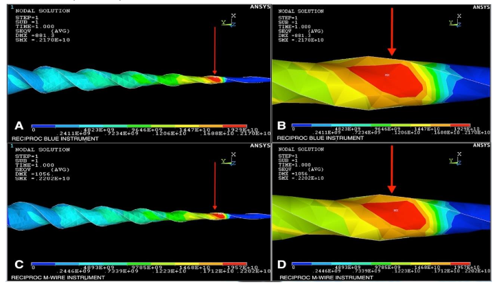
Legend: The red arrow in A and C shows the point of maximum stress (in red) and the point defined for measuring the maximum angle of rotation of the Reciproc Blue and Reciproc. B and D show the stress point in an enlarged view.
Discussion
This study employed the ISO 3630-1 standard torsion test to assess the maximum torsional strength and rotation angle of the instruments could endure before failure, a method acclaimed as the benchmark for accuracy in evaluating torsional properties¹⁶˒¹⁷. The study’s findings revealed no significant difference between the in vitro torsion and finite element model tests, so the null hypothesis was accepted.
To validate the FEM of the endodontic instruments, comparison parameters were established. The in vitro torsion test results align with previous studies⁸˒¹⁶, where research indicates that the fracture stress for NiTi alloys (M-wire and Blue) is approximately 1540 MPa⁵˒¹⁴. By comparing these data with the FEM output, we could assess whether the model replicated the experimental behavior accurately.
Under the applied loads, failure in the Reciproc R25.08 (M-Wire) and Reciproc Blue R25.08 instruments during in vitro testing occurred within the first 3 mm at an average torque of 1.4 ± 0.1295 N·cm and 1.38 ± 0.1392 N·cm, respectively. The finite element simulations loaded the models with torques matching these averages to verify the model’s accuracy. The resulting stress concentrations, depicted in Figure 1, confirmed that maximum stress values, ranging from 1667.9 MPa to 1877.6 MPa, focused around 3 mm from the instrument tip. These stress levels exceeded the NiTi fracture threshold (1540 MPa), indicating the instruments would likely fail at this point, supporting the model’s validity.
The angular deflection at failure was evaluated to assess the stress needed to cause breakage within the first 3 mm from the instrument tip. As previously noted, failure consistently occurred in this region, indicated by the red area in Figure 1. Therefore, identifying the maximum rotation angle at this point is crucial, as reaching this angle would result in instrument failure. The angular rotation was determined by converting the node displacement values in this area into angles using Equation 1. The FEM-predicted angles closely matched those from the in vitro experiments, showing no significant differences.
Comparing the results from both methods, a slight discrepancy was noted between the numerical and experimental outcomes for the Reciproc M-Wire instrument, with a 10.84% difference and a 6.16% difference for the Reciproc Blue. This variance can be attributed to multiple factors that might affect the model, including:
i) Instrument fixation, which was done using a mandrel; the applied force could create small deformations leading to micro-cracks and reduced torsion strength.
ii) Manual alignment during fixation could introduce slight deviations from axis alignment, inducing bending stresses and deviating from pure torsional loading.
iii) Manufacturing inconsistencies might lead to dimensional or quality variations affecting the results.
iv) While the experimental torque value was average with standard deviation across multiple instruments, the numerical model applied an exact torque value¹⁸.
Numerous studies have utilized FEMs to explore endodontic instrument mechanics, but many lack comparison with experimental data⁵˒¹⁴˒¹⁹. This study’s contribution lies in validating finite element results against experimental data, demonstrating their close alignment. This validation supports the use of FEM for efficient and cost-effective analysis of instrument torsional behavior, by passing the need for numerous costly physical samples.
Conclusion
Our findings confirm that the FEM yields results that are accurate and comparable to ISO 3630-1 in vitro torsion tests. Thus, this model is a viable tool for evaluating the mechanical behavior of NiTi instruments. The use of FEM not only expedites the testing process but also reduces costs and methodological biases, offering a reliable method for future studies.
Conflict of Interest
The authors have no conflicts of interest to declare.
Funding Statement
No financial disclosure.
References
1. Bahrami B, Shahrbaf S, Mirzakouchaki B, Ghalichi F, Ashtiani M, Martin N. Effect of surface treatment on stress distribution in immediately loaded dental implants–a 3D finite element analysis. Dent Mater. 2014;30(4):e89-97. doi:10.1016/j.dental.2014.01.012
2. Akkoç Hİ, Keskin C, Aslantaş K. Dynamic analysis of a NiTi rotary file by using finite element analysis: Effect of cross-section and pitch length. Aust Endod J. Published online October 3, 2024. doi:10.1111/aej.12892
3. Roda-Casanova V, Pérez-González A. Computerized Generation of Endodontic Files by Reproducing the Flute Grinding Manufacturing Process. Bioengineering (Basel). 2024;11(8). doi:10.3390/bioengineering11080751
4. Eken R, Sen OG, Eskitascioglu G, Belli S. Evaluation of the Effect of Rotary Systems on Stresses in a New Testing Model Using a 3-Dimensional Printed Simulated Resin Root with an Oval-shaped Canal: A Finite Element Analysis Study. J Endod. 2016;42(8):1273-1278. doi:10.1016/j.joen.2016.05.007
5. El-Anwar MI, Yousief SA, Soliman TA, Saleh MM, Omar WS. A finite element study on stress distribution of two different attachment designs under implant supported overdenture. Saudi Dent J. 2015;27(4):201-207. doi:10.1016/j.sdentj.2015.03.001
6. De-Deus G, Leal Vieira VT, Nogueira da Silva EJ, Lopes H, Elias CN, Moreira EJ. Bending resistance and dynamic and static cyclic fatigue life of Reciproc and WaveOne large instruments. J Endod. 2014;40(4):575-579. doi:10.1016/j.joen.2013.10.013
7. Yoo YS, Cho YB. A comparison of the shaping ability of reciprocating NiTi instruments in simulated curved canals. Restor Dent Endod. 2012;37(4):220-227. doi:10.5395/rde.2012.37.4.220
8. Alcalde MP, Duarte MAH, Bramante CM, de Vasconselos BC, Tanomaru-Filho M, Guerreiro-Tanomaru JM, et al. Cyclic fatigue and torsional strength of three different thermally treated reciprocating nickel-titanium instruments. Clin Oral Investig. 2018;22(4):1865-1871. doi:10.1007/s00784-017-2295-8
9. Ajuz NCC, Armada L, Gonçalves LS, Debelian G, Siqueira JF. Glide path preparation in S-shaped canals with rotary pathfinding nickel-titanium instruments. J Endod. 2013;39(4):534-537. doi:10.1016/j.joen.2012.12.025
10. Gharechahi M, Moezzi S, Karimpour S. Comparative Analysis of Stress Distribution through Finite-Element Models of 3 NiTi Endodontic Instruments while Operating in Different Canal Types. J Dent (Shiraz). 2023;24(1):60-65. doi:10.30476/DENTJODS.2022.90785.1522
11. Martins JNR, Pinto R, Silva EJNL, Simões-Carvalho M, Marques D, Martins RF, et al. 3D Surface Scanning-A Novel Protocol to Characterize Virtual Nickel-Titanium Endodontic Instruments. Materials (Basel). 2023;16(10). doi:10.3390/ma16103636
12. Montalvão D, Alçada FS, Braz Fernandes FM, de Vilaverde-Correia S. Structural characterisation and mechanical FE analysis of conventional and M-Wire Ni-Ti alloys used in endodontic rotary instruments. ScientificWorldJournal. 2014;2014:976459. doi:10.1155/2014/976459
13. Chien PYH, Walsh LJ, Peters OA. The extended finite element method in endodontics: A scoping review and future directions for cyclic fatigue testing of nickel-titanium instruments. Clin Exp Dent Res. 2024;10(3):e893. doi:10.1002/cre2.893
14. Bonessio N, Pereira ESJ, Lomiento G, Arias A, Bahia MGA, Buono VTL, et al. Validated finite element analyses of WaveOne Endodontic Instruments: a comparison between M-Wire and NiTi alloys. Int Endod J. 2015;48(5):441-450. doi:10.1111/iej.12333
15. Wakabayashi N, Ona M, Suzuki T, Igarashi Y. Nonlinear finite element analyses: advances and challenges in dental applications. J Dent. 2008;36(7):463-471. doi:10.1016/j.jdent.2008.03.010
16. Alcalde MP, Tanomaru-Filho M, Bramante CM, Duarte MAH, Guerreiro-Tanomaru JM, Camilo-Pinto J, et al. Cyclic and Torsional Fatigue Resistance of Reciprocating Single Files Manufactured by Different Nickel-titanium Alloys. J Endod. 2017;43(7):1186-1191. doi:10.1016/j.joen.2017.03.008
17. Vivan RR, Alcalde MP, Candeiro G, Gavini G, Caldeira CL, Duarte MAH. Torsional fatigue strength of reciprocating and rotary pathfinding instruments manufactured from different NiTi alloys. Braz Oral Res. 2019;33:e097. doi:10.1590/1807-3107bor-2019.vol33.0097
18. García-Braz SH, Prados-Privado M, Zanatta LCS, Calvo-Guirado JL, Prados-Frutos JC, Gehrke SA. A Finite Element Analysis to Compare Stress Distribution on Extra-Short Implants with Two Different Internal Connections. J Clin Med. 2019;8(8). doi:10.3390/jcm8081103
19. Necchi S, Petrini L, Taschieri S, Migliavacca F. A comparative computational analysis of the mechanical behavior of two nickel-titanium rotary endodontic instruments. J Endod. 2010;36(8):1380-1384. doi:10.1016/j.joen.2010.03.026
Most read articles by the same author(s)
- Luana V. R. Bueno, Ana Grasiela Limoeiro, Luanna Sales da Silva Vasconcellos, Michel Klymus, Alexandre Sigrist De Martin, Rina Andrea Pelegrine, Carolina Pessoa Stringheta, Carlos Eduardo Fontana, Marília Fagury Marceliano-Alves, Murilo Priori Alcalde, Marco Antônio Húngaro Duarte, Carlos Eduardo da Silveira Bueno, Evaluation of apical extrusion of debris after instrumentation with two reciprocating systems: RC Blue and Reciproc Blue , Medical Research Archives: Vol 13 No 11 (2025): Vol.13, Issue 11, November 2025